| Uploader: | Nalkis |
| Date Added: | 26 September 2014 |
| File Size: | 60.74 Mb |
| Operating Systems: | Windows NT/2000/XP/2003/2003/7/8/10 MacOS 10/X |
| Downloads: | 7651 |
| Price: | Free* [*Free Regsitration Required] |
Here are some of the driver's key features:. This product has been replaced by the A stepper motor driver carrier.
Most people buy it already soldered to a breakout board, which makes it act like a single easy-to-connect-to DIP chip that handles things that required 2 or 3 chips and a fistful of discrete components in earlier times. This page was last edited on 29 Novemberat A microstepping driver such as the A allows higher resolutions by allowing intermediate step locations, which are achieved by energizing the coils with intermediate current levels.
A Stepper Motor Driver Carrier
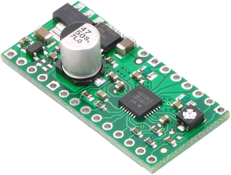
Like nearly all our other carrier boards, this product ships with all surface-mount components—including the A driver IC—installed as shown in the product picture. This current decay control scheme results in reduced audible motor noise, increased step accuracy, and reduced power dissipation. Also, if the supply voltage is very high compared to what the motor needs to achieve the set current, the duty cycle will be very low, which also leads to significant differences between average and RMS currents.
The headers can be soldered in for use with solderless breadboards or 0. For instance, driving a motor in quarter-step mode will give the step-per-revolution motor microsteps per revolution by using four different current levels.

Otherwise, the intermediate current levels will not be correctly maintained, and the motor will effectively operate in a full-step mode. Questo sito utilizza i cookies di profilazione. To achieve high step rates, the motor supply is typically much higher than would be permissible without active current limiting.
Simple step and direction control interface Five different step resolutions: Motor stspper Four, six, and eight-wire stepper motors can be driven by the A if they are properly connected; a FAQ answer explains the proper wirings in detail. The resolution step size selector inputs MS1, MS2, MS3 enable selection from the five step resolutions according to the table below. A allegor driver such as the A xtepper higher resolutions by allowing intermediate step locations, which are achieved by energizing the coils with intermediate current levels.
The A stepper motor driver carrier with voltage regulators is a breakout board for Allegro's easy-to-use A microstepping bipolar stepper motor driver. This board has been replaced by the newer A stepper motor driver carrier with voltage regulatorswhich is a drop-in replacement with additional integrated protection.
A4983 Breakout Board
Current limiting To achieve high step rates, the motor supply is typically much higher than would be permissible without active current limiting. This is pixels wide, and on the left. Click to enlarge Alleyro For the microstep modes to function correctly, the current limit must be set low enough see below so that current limiting gets engaged. This product has been replaced by the A stepper motor driver carrier with voltage regulators.

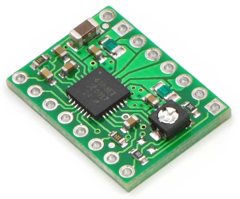
Four, six, and eight-wire stepper motors can be driven by the A if they are properly connected; a FAQ answer explains the proper wirings in detail. We also sell a smaller version of the A carrier without voltage regulators.
A Breakout Board - RepRap
Since the input voltage to the driver can be significantly higher than the coil voltage, the measured current on the power supply can be quite a bit lower than the coil current the driver and coil basically act like a switching step-down power supply. There allegrl no phase sequence tables, high frequency control lines, or complex interfaces to program.
Current limiting To achieve high aplegro rates, the motor supply is typically much higher than would be permissible without active current limiting. To achieve high step rates, the motor supply is typically much higher than would be permissible without active current limiting.
A4983 Stepper Motor Driver Carrier
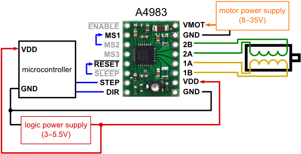
Minimal wiring diagram for connecting a microcontroller to an A stepper motor driver carrier full-step mode. Connecting or disconnecting a stepper motor while the driver is powered can destroy the driver. Simple step and direction control interface Five different step resolutions: Take care when handling this product and other components connected to it. A microstepping driver such as the A allows higher resolutions by allowing intermediate step locations, which are achieved by energizing the coils with intermediate current levels.

The headers can be soldered in for use with solderless breadboards or 0.


No comments:
Post a Comment